ESP32 7 Segment Display (1 Digit) with Arduino IDE
## Introduction A 7-segment display is used to show numeric digits using 7 LEDs (segments) labeled a–g. Each segment is controlled individually to display numbers from 0 to 9. Available in Common Cathode or Common Anode types. In this tutorial, we’ll connect and control a 1-digit 7-segment display u
#Introduction
A 7-segment display is used to show numeric digits using 7 LEDs (segments) labeled a–g.
Each segment is controlled individually to display numbers from 0 to 9.
Available in Common Cathode or Common Anode types.
In this tutorial, we’ll connect and control a 1-digit 7-segment display using the ESP32.
#Required Components
- ESP32 Board
- 7 Segment Display
- 220 Ohm Resistor (8 Pcs)
- Jumper wires
- Breadboard
#Pinout

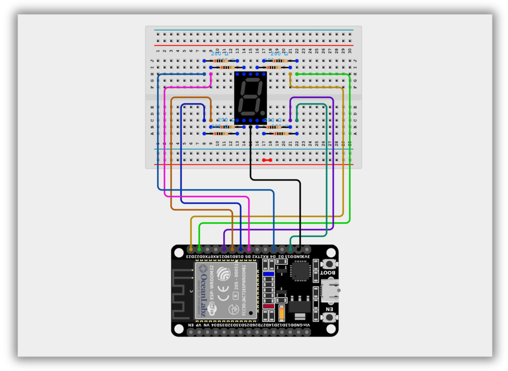
#Circuit Diagram / Wiring
- Segment (a) → ESP32 GPIO 23
- Segment (b) → ESP32 GPIO 22
- Segment (c) → ESP32 GPIO 21
- Segment (d) → ESP32 GPIO 19
- Segment (e) → ESP32 GPIO 18
- Segment (f) → ESP32 GPIO 5
- Segment (g) → ESP32 GPIO 4
- Segment (DP) → ESP32 GPIO 15
- Segment (GND) → ESP32 GND
- Use 220Ω resistors between each segment pin and the ESP32 to limit current.
#Code / Programming
/* Filename: esp32_7segment_display.ino Description: Display digits 0–9 on a common cathode 7-segment display using ESP32 Author: www.oceanlabz.in Modification: 1/4/2025 */
// Define ESP32 GPIO pins connected to segments a-g const int a = 23; const int b = 22; const int c = 21; const int d = 19; const int e = 18; const int f = 5; const int g = 4;
// Segment patterns for digits 1 to 9 (0 = ON for Common Cathode) byte digits[10][7] = { // a, b, c, d, e, f, g {1, 1, 1, 1, 1, 1, 0}, // 0 {0, 1, 1, 0, 0, 0, 0}, // 1 {1, 1, 0, 1, 1, 0, 1}, // 2 {1, 1, 1, 1, 0, 0, 1}, // 3 {0, 1, 1, 0, 0, 1, 1}, // 4 {1, 0, 1, 1, 0, 1, 1}, // 5 {1, 0, 1, 1, 1, 1, 1}, // 6 {1, 1, 1, 0, 0, 0, 0}, // 7 {1, 1, 1, 1, 1, 1, 1}, // 8 {1, 1, 1, 1, 0, 1, 1} // 9 };
// Store segment pins in an array const int segmentPins[7] = {a, b, c, d, e, f, g};
void setup() { for (int i = 0; i < 7; i++) { pinMode(segmentPins[i], OUTPUT); } }
void loop() { for (int i = 1; i <= 9; i++) { displayDigit(i); delay(1000); } }
// Function to display a digit void displayDigit(int num) { for (int i = 0; i < 7; i++) { digitalWrite(segmentPins[i], digits[num][i]); } }
#Explanation
- A 7-segment display uses seven individual LEDs (a–g) to form numeric digits.
- The ESP32 controls each segment through digital GPIO pins to display numbers from 1 to 9.
- This project demonstrates how to light up each digit sequentially using a common cathode display.
#Troubleshooting
- If segments are not lighting correctly, double-check wiring and pin assignments.
- For dim or no display, ensure resistors are properly rated (e.g., 220Ω) and common cathode is grounded.
- If using a common anode display, invert the HIGH/LOW logic in
digitalWrite().