ESP32 Matrix Display with Arduino IDE
## **Introduction** The MAX7219 8×8 LED Matrix module is a versatile component used to display text, numbers, and animations. It simplifies the process of controlling individual LEDs in the 8×8 matrix using the MAX7219 chip. This tutorial will guide you through connecting the matrix module to an ESP
#Introduction
The MAX7219 8×8 LED Matrix module is a versatile component used to display text, numbers, and animations.
It simplifies the process of controlling individual LEDs in the 8×8 matrix using the MAX7219 chip.
This tutorial will guide you through connecting the matrix module to an ESP32 and programming it to display simple patterns, text, or scrolling messages.
#Required Components
- ESP32 Board
- 8×8 LED Matrix Display Module
- Jumper wires
- Breadboard
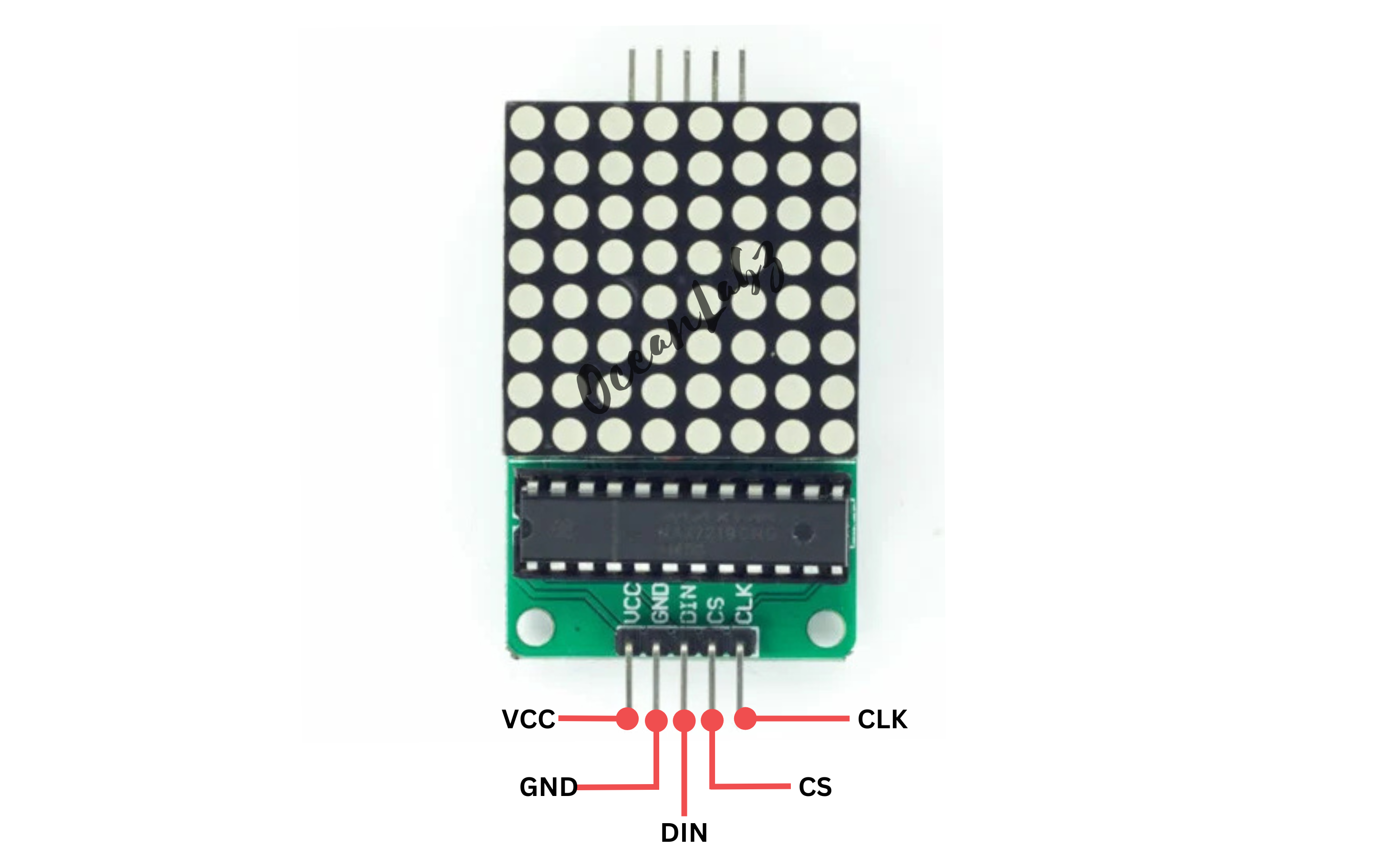
#Pinout
#Circuit Diagram / Wiring
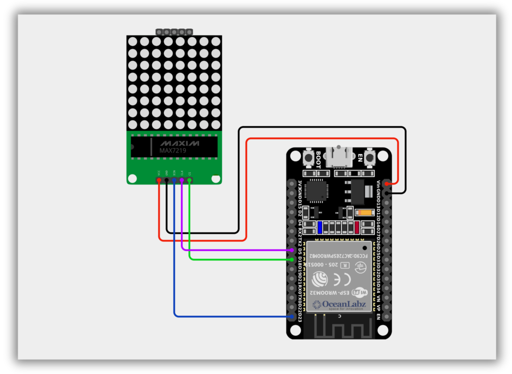
- VCC (LED Module) → VIN/5V (ESP32)
- GND (LED Module) → GND (ESP32)
- DIN (LED Module) → Pin 32(ESP32)
- CS (LED Module) → Pin 5(ESP32)
- CLK (LED Module) → Pin 18(ESP32)
#Code / Programming
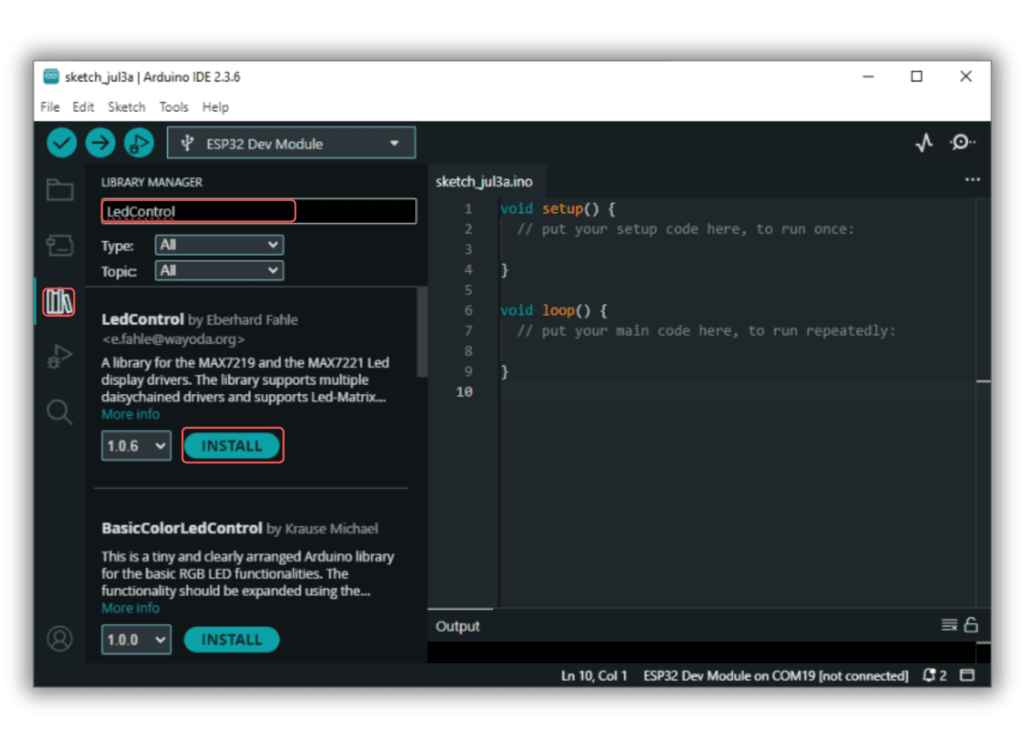
- Install Required Library (via Arduino Library Manager).
- Go to the “Libraries” tab on the left-hand side of the screen.
- Click on the “Library Manager” button (book icon) at the top of the Libraries tab.
- In the Library Manager window, type “LedControl” in the search bar.
- Locate the “LedControl” library click on the “Install” button next to it.
- Wait for the library to be installed, and you’re ready to use the LedControl library in your projects.
/* Filename: esp32_led_matrix_display.ino Description: Displays animated patterns (face, heart, smiley) on 8x8 LED matrix using MAX7219 and ESP32 Author: www.oceanlabz.in Modified: 1/4/2025 */
#include <SPI.h>
// ESP32 Pin Definitions #define DATA_IN 23 // DIN (MOSI) #define CLK 18 // CLK (SCK) #define CS 5 // LOAD/CS
// MAX7219 registers #define MAX7219_REG_NOOP 0x00 #define MAX7219_REG_DIGIT0 0x01 #define MAX7219_REG_DIGIT1 0x02 #define MAX7219_REG_DIGIT2 0x03 #define MAX7219_REG_DIGIT3 0x04 #define MAX7219_REG_DIGIT4 0x05 #define MAX7219_REG_DIGIT5 0x06 #define MAX7219_REG_DIGIT6 0x07 #define MAX7219_REG_DIGIT7 0x08 #define MAX7219_REG_DECODEMODE 0x09 #define MAX7219_REG_INTENSITY 0x0A #define MAX7219_REG_SCANLIMIT 0x0B #define MAX7219_REG_SHUTDOWN 0x0C #define MAX7219_REG_DISPLAYTEST 0x0F
// Define the bitmaps const uint8_t normalFace[8] = { B00111100, B01000010, B10100101, B10000001, B10000001, B10111101, B01000010, B00111100 };
const uint8_t heart[8] = { B00000000, B01100110, B11111111, B11111111, B11111111, B01111110, B00111100, B00011000 };
const uint8_t smileFace[8] = { B00111100, B01000010, B10100101, B10000001, B10100101, B10011001, B01000010, B00111100 };
void writeMAX7219(uint8_t reg, uint8_t data) { digitalWrite(CS, LOW); SPI.transfer(reg); SPI.transfer(data); digitalWrite(CS, HIGH); }
void setup() { pinMode(CS, OUTPUT); pinMode(DATA_IN, OUTPUT); pinMode(CLK, OUTPUT);
SPI.begin(CLK, -1, DATA_IN, CS); SPI.setDataMode(SPI_MODE0); SPI.setBitOrder(MSBFIRST); SPI.setFrequency(1000000);
// Initialize MAX7219 writeMAX7219(MAX7219_REG_SHUTDOWN, 0x01); // Wake up writeMAX7219(MAX7219_REG_DECODEMODE, 0x00); // No decoding writeMAX7219(MAX7219_REG_SCANLIMIT, 0x07); // Display all 8 digits writeMAX7219(MAX7219_REG_INTENSITY, 0x08); // Medium brightness writeMAX7219(MAX7219_REG_DISPLAYTEST, 0x00); // No test clearDisplay(); }
void clearDisplay() { for (int row = 0; row < 8; row++) { writeMAX7219(MAX7219_REG_DIGIT0 + row, 0x00); } }
void displayPattern(const uint8_t *pattern) { for (int row = 0; row < 8; row++) { writeMAX7219(MAX7219_REG_DIGIT0 + row, pattern[row]); } }
void loop() { displayPattern(normalFace); delay(1000);
clearDisplay(); delay(500);
displayPattern(heart); delay(1000);
clearDisplay(); delay(500);
displayPattern(smileFace); delay(1000);
clearDisplay(); delay(500); }
#Explanation
- The MAX7219 chip controls an 8×8 LED matrix using just 3 GPIO pins from the ESP32 (DIN, CLK, CS).
- The ESP32 sends patterns or characters to the matrix through SPI-like serial communication using the
LedControllibrary. - By defining custom byte arrays, you can display emojis, animations, or scrolling messages on the matrix.
#Troubleshooting
- If nothing displays, double-check the wiring order (DIN, CLK, CS) and ensure VCC is 5V.
- Make sure the correct GPIO pins are used and match those in
LedControlinitialization. - If brightness is too low or LEDs flicker, increase brightness using
lc.setIntensity(0, level)(0–15).